Open Systems Interconnection
1. Open Systems Interconnection
MODULE TWO
2. 0 Introduction
The OSI (Open Systems Interconnection) Model is a conceptual framework that describes how different computer systems communicate over a network. It was developed by the International Organization for Standardization (ISO) in 1984 to standardize networking protocols and ensure interoperability between different devices and technologies. The model consists of seven layers, each with a specific function in the process of data transmission. These layers work together to facilitate communication between devices, whether they are in the same network or across the globe.
2. 1 OSI 7 LAYER MODEL
OSI stands for Open Systems Interconnection. It was developed by ISO – ‘International Organization for Standardization’, in the year 1984. It is a 7-layer architecture with each layer having specific functionality to perform. All these 7 layers work collaboratively to transmit the data from one person to another across the globe. It describes how a data transfers over the network from one system to the other and the way the systems send information to one another. In order to accomplish a successful communication between systems, there are 7 distinct layers that are interconnected and work closely to make the communication happen. These are; application layer, presentation layer, session layer, transport layer, network layer, data link layer, and physical layer.
The purpose of the OSI model is to enable functionality and interoperability between different vendors and connectors. From the design point of view, it divides layer tasks into smaller more manageable layers as shown in figure 2.1. Example of how the data flows in an OSI model is when you send an email to a friend. The email has to pass to presentation layer through the application layer. The data get compressed at this layer. The session layer initializes communications that will then be segmented in the transportation layer. The segments are broken up into packets in the network layer and then frames in the data link layer that will then be sent to the physical layer where it is converted into 0s and 1s and then sent through a physical medium like cables. when your friend gets the email through the physical medium, the data flows through the same layers but in the opposite order i.e., the process start from the physical layer up to the application layer. The physical converts the 0s and 1s to frames that will be passed to the data link layer. This will be reassembling the frames into packets for the next layer. The network layer will assemble the segments into data. The data is then passed on to the presentation layer which ends the communication session. The presentation layer will then pass the data to the application layer.
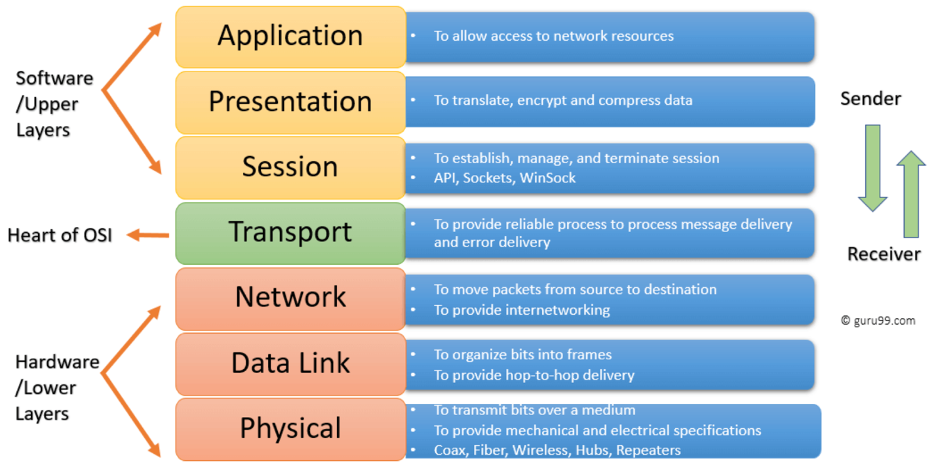
Figure 2.1: Network OSI Layers Model
The Upper Layers: It deals with application issues and mostly implemented only in software. The highest is closest to the end system user as depicted in figure 2.1. In this layer, communication from one end- user to another begins by using the interaction between the application layer. It will process all the way to end- user.
The Lower Layers: These layers handle activities related to data transport. The physical layer and datalink layers also implemented in software and hardware as seen in figure 2.1.
LAYER 1: PHYSICAL LAYER
This layer is the lowest layer of the OSI Model. It is responsible for transmitting unstructured data bits across the network, it is the layer that stands between the sending and receiving devices. That is, it takes care of the transmission of raw bits streams. The physical layer includes physical resources such as cables, modem, network adaptors and hubs.
Functions of Physical Layer of OSI Model
- It enables bit synchronization using a clock that controls both sender and receiver.
- It also controls the transmission rate or several bits sent per second.
- This layer decides the ideal topology type for node arrangement in a network. i.e. bus, star, or mesh topology.
- defines how the data flows between the two connected devices. That is, it decides the transmission mode between the devices. The various transmission modes possible are Simplex, half-duplex and full-duplex.
LAYER 2: DATA LINK LAYER
This layer corrects any errors that may have occurred at the physical layer. It ensures that any data transfer is error free between the nodes over the physical layer. It is responsible for reliable transmission of data frames between connected nodes. The data is packaged into frames in this layer. Data link has 2 sub layers:
1. Media Access Control (MAC): The MAC address layer is responsible for flow control and multiplexing devices transmissions over the network.
2. Logical Link Control: Provides error control and flow control over the physical medium and identifies line protocols
Functions of Data Link Layer of OSI Model
- It frames the data in a way that is meaningful to the receiver using special bit patterns.
- It adds physical addresses of both sender and receiver in every frame.
- This layer controls error by detecting and retransmitting frames.
- It controls the flow by calculating the amount of data before receiving it.
- It determines the extent of control devices have in a given time.
- Network Interface Card handles this layer using devices like switch & bridge
LAYER 3: NETWORK LAYER
This layer receives frames from the data link layer and delivers them to the intended destination based on the addresses inside the frames. It handles packets routing. The network layer locates destinations using logical addresses like IP address. Routers are crucial components at this layer as they route information to where it needs to go between different networks.
Functions of Network Layer of OSI Model
The main functions of the network layer are:
§ Routing: the network layer protocols determine which routes from source to destination.
§ Logical Addressing: the network layer defines an addressing scheme into uniquely identifying devices. The network layer places the IP addresses from the sender and receiver in the header.
LAYER 4: TRANSPORT LAYER
The transport layer is responsible for delivering, error checking, flow control and sequencing data packets. It regulates the sequencing, size and transfer of data between systems and hosts. This layer gets the data from the session layer and breaks it into transportable segments Protocols from transport layer or Transmission Control Protocol (TCT) and User Datagram Protocol (UDP).
a. Transmission Control Protocol
A standard protocol for internet communication between hosts. It divides data into smaller segments that travel using multiple internet routes to reach the destination. It also corrects the order of the packets at the receiving end. TCT is built on top of the Internet Protocol (IP), commonly known as TCP/IP. TCP and UDP port numbers work at Layer 4, while IP addresses work at Layer 3, the Network Layer.
b. User Datagram Protocol (UDP)
It is a transport layer protocol that is quite unreliable. The receiver does not receive any acknowledgment and the sender doesn’t even try to send it.
Functions of Transport Layer
- It accepts data and breaks into smaller units while sending. And it reassembles the data while receiving.
- It follows a service point address to deliver the message to the correct process.
Transport layer performs 2 types of services:
i. Connection Oriented Transmission: this is carried out via wire connection. This transmission is done by UDP. The UDP is faster than TCP because it does not provide feedback whether the data has really transferred whereas, TCP provides feedback, therefore, load data can be transmitted in TCP.
ii. Connectionless Transmission: by using data transfer. The receiver doesn’t get an acknowledged receipt but the process is faster.
LAYER 5: SESSION LAYER
The session layer creates communication channels called “sessions” between different devices. It is responsible for opening those sessions and ensuring that they’re functional during data transfer. That is; the session layer is responsible for establishing, managing and terminating communication sessions with remote and local applications. They can also choose to terminate a complete session/transmission. It is also responsible for authentication and reconnections and it can set checkpoints during a data transfer
Functions of Session Layer
§ Functions at this layer involve setup, coordination (how long should a system wait for a response, for example) and termination between the applications at each end of the session.
§ The layer can easily process the establishment, use, and termination of a connection.
§ It adds checkpoints as synchronization points into the data for identifying the error easily and avoiding data loss.
§ Two systems can also interact with each other in half-duplex or full-duplex.
LAYER 6: PRESENTATION LAYER
Presentation layer is also known as “syntax layer”. The presentation layer is responsible for ensuring that the data is understandable for the end system or useful for later layer. It translates or formats data based on the application syntax or semantics. It also manages any encryption or decryption required by the application layer. This layer receives data from application layer and converts ASCII format to machine code/language. In other words, it represents the preparation or translation of application format to network format, or from network formatting to application format.
Functions of Presentation Layer
- Character code translation from ASCII to EBCDIC.
- Data compression: Allows to reduce the number of bits that needs to be transmitted on the network.
- Data encryption: Helps you to encrypt data for security purposes — for example, password encryption.
- It provides a user interface and support for services like email and file transfer.
LAYER 7: APPLICATION LAYER
The application layer feeds the human readable data to the email software that will allow your friend to read. The application layer is where the user interacts with the software application. So, it is the closest to the end user. This layer interacts with the application communicating with the network. the application layer is used by the network applications which rely on application layer protocols like HTTP, and HTTPS to function. The applications that use these protocols are browsers, Firefox, Google Chrome, Outlook and Skype e.t.c. there are many application layer protocols that enable functions at this layer. All these protocols collectively are called application layer. Application layer provides services for network applications. With the help of these protocols, users are able to perform activities like sending email, file transfer, web surfing e.t.c. file transfer is done with the help of FTP protocols, SMTP protocol for sending email, HTTP or HTTPS is used for web surfing and TelNet for virtual terminals. Application layer provides services for network application.
Functions of Presentation Layer
- Application-layer helps you to identify communication partners, determining resource availability, and synchronizing communication.
- It allows users to log on to a remote host
- File management by allowing users to access, retrieve and manage the files on a remote computer.
- This application provides distributed database sources and access for global information about various objects and services.
NOTE:
I. File Transfer Protocol (FTP): File Transport Protocol or FTP is a client-initiated transfer where the client can receive a file or can send a file to the server. The specific type of transmission, as well as the level of security, is determined by the server. It’s an internet TCP protocol, used to transfer files between one client computer to a server. Widely used to publish websites, transfer images, backups or any kind of files.
II. Simple mail transfer protocol (SMTP) is defined as an email protocol that enables the transmission of emails among user accounts over an internet connection. Simply put, SMTP is a set of rules that allows different email accounts and clients to streamline information exchange.
III. Telnet is a network protocol that allows a user to remotely access and control another computer over the Internet or local area network (LAN). It enables a user to establish a connection to a remote system and perform tasks as if they were sitting in front of that computer.
The example provided below explains this:
Every layer in an OSI model is in communication with both its peer layer in another networked computing system and the other two levels that are below it as showed in figure 2.2. The data link layer of the first system communicates with the network layer and the physical layer of the system, as shown in the picture below. It also facilitates communication with the second system's data link layer.
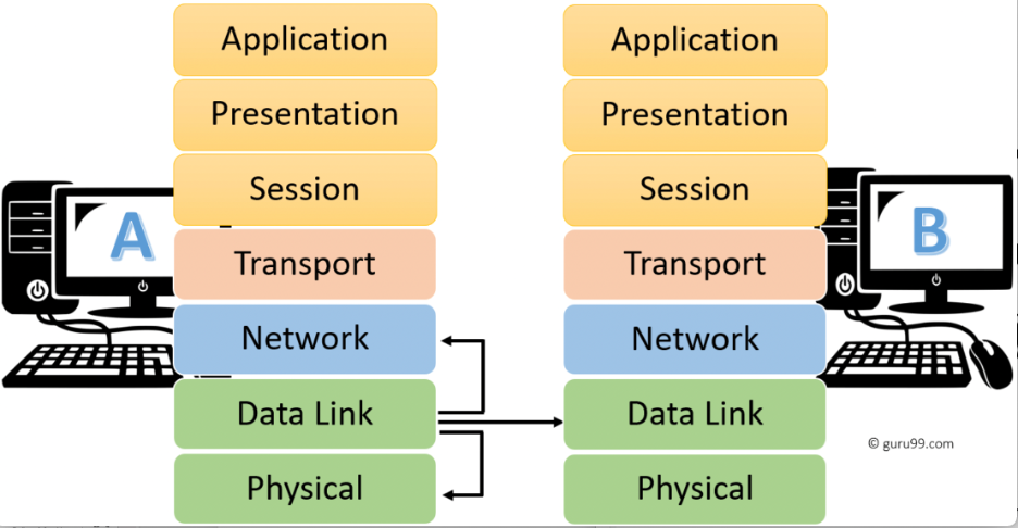 Figure 2.2: Communication
between the Network OSI Model
Figure 2.2: Communication
between the Network OSI Model
In a nutshell the OSI 7 layers is summarized in table below:
|
Layer No |
Layer |
Function |
Device or Protocol |
|
7 |
Application Layer |
Helps in identifying the client and synchronizing communication. Gives access to network resources |
SMTP, HTTP, FTP |
|
6 |
Presentation Layer |
Data from the application layer is extracted and manipulated in the required format for transmission. Responsible for translating, encrypting, and compressing data. |
JPEG, MPEG, GIF |
|
5 |
Session Layer |
Establishes Connection, Maintenance, Ensures Authentication, and Ensures security. |
Gateway, NetBIOS, SAP |
|
4 |
Transport Layer |
Take Service from Network Layer and provide it to the Application Layer. Enables data transport from source to destination machine |
TCP, UDP, Firewall |
|
3 |
Network Layer |
Transmission of data from one host to another, located in different networks. Provides internetworking and packet movement |
Router, IPV5-6, ARP |
|
2 |
Data Link Layer |
Organize bits into frames. Node to Node Delivery of Message. |
Switch, Bridge |
|
1 |
Physical Layer |
Establishing Physical Connections between Devices. Responsible for providing mechanical and electrical specifications |
Hub, Repeater, Modem, Cables |