CURRENT ELECTRICITY
3. OHM'S LAW AND SIMPLE DC CIRCUIT ANALYSIS
Ohm’s law gives the relationship between voltage, current and resistance in a simple DC circuit. V = IR. Equivalent,  . In addition, this implies that current is directly proportional to voltage if resistance is constant and also current is inversely to resistance is voltage remains constant.
Simple DC circuit
In direct current (DC) circuits, the voltage, source (Battery, power supply) maintains a constant polarity and magnitude of voltage. We assume the circuit is made of resistors an wires with negligible resistance.
Common DC configuration
Series connection
In a series connection, resistors are connected end to end, so that the current flows through each resistor in turn. The total resistance of the series connection is equal to the sum of the individual resistances of the resistors. The current through each resistor in a series connection is the same, and the voltage across the series connection is divided among the resistors in proportion to their resistance.
Let three resistors R1, R2 and R3 as shown below
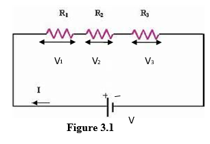
Let V= Voltage applied across the series combination
I = Current passing through the circuit
Clearly current I is same throughout the circuit
Let V1, V2, V3 be the potential difference across R1, R2, R3 respectively. Then, according to Ohm’s law
V = I R
where R is the total resistance in series
Now
V = V1 + V2 + V3 --------------- (1)
Then by Ohm’s law
V1 = I R1
V2 = I R2
V3 = I R3
Putting the values of V1, V2 and V3 in equation (1) we get
IR = I R1+I R2 +I R3
IR = I (R1 +R2 + R3)
R = (R1+R2+ R3)
Thus, the combined resistances when they are connected in series is the sum total of the individual resistances.
Characteristics of Resistors in series
- Same current: The same electric current flows through every resistor because there is only one path for current.
- Total resistance increases: The total resistance is the sum of all the individual resistances.
- Voltage is shared: The supply voltage is divided among the resistors. The voltage drops across each resistor depends on its resistance.
- Higher resistance gets a higher voltage drop: If the same current flows through different resistors, the resistor with the greatest resistance has the greatest voltage drop, according to Ohm’s law.
- Failure of one resistor breaks the circuit: If one resistor becomes open-circuit, current stops flowing through all the resistors.
- Equivalent resistance is greater than any individual resistance: For positive resistance values, the total resistance is greater than each individual resistor.
- Current decreases when more resistance is added: If the supply voltage remains constant, adding another resistor in series increases the total resistance and reduces the current.
Parallel connection
In a parallel connection, resistors are connected across each other, so that the voltage across each resistor is the same. The total resistance of the parallel connection is less than the smallest individual resistance of the resistors. The current through each resistor in a parallel connection is divided among the resistors in proportion to their resistance.
Let there be three resistors R1, R2, R3 connected in parallel as shown in Figure 3.2. One end of each resistance is connected to point A and the other end of each resistance is connected to the point B.
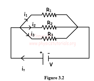
Let V = Potential Difference applied across A and B clearly, potential difference V is same across each resistance.
Let I = total current flowing in the circuit.
R = total resistance of the circuit
Let I1, I2, I3 be the current passing through the resistances R1, R2, R3 respectively. From Ohm’s law applied to the whole circuit.
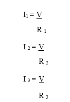
Now we have,
I = I1+ I2+ I3 ----------------------- (2)
Putting the values of I, I1, I2, I 3 in the equation (2)
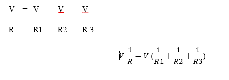
OR
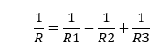
Thus, we can say that if the resistors are connected in parallel, then the reciprocal of the equivalent resistance is equal to the sum of reciprocals of individual resistances in the circuit.
Characteristics of Resistors in Parallel
- Same voltage: The voltage across each resistor is equal to the supply voltage
- Current is divided: The total current divides among the different branches. The amount flowing through each resistor depends on its resistance.
- Total resistance decreases: The reciprocal of the total resistance equals the sum of the reciprocals of the individual resistances.
- Total resistance is less than the smallest resistor: Adding more parallel resistors provides additional paths for current, reducing the equivalent resistance.
- Failure of one branch does not necessarily stop the others: If one resistor becomes open-circuit, current can still flow through the other parallel branches.
- Adding more resistor increases total current: When the supply voltage remains constant, adding another parallel resistor decreases the total resistance and increases the total current drawn from the supply
- A lower resistance carries more current: For the same voltage across each branch, a resistor with lower resistance carries a greater current, according to Ohm’s law.
Examples
1) Calculate the total resistance when resistors of 2Ω and 3Ω are connected in parallel.
2) Calculate the total resistance when three resistors of 4Ω, 8Ω, and 14Ω are connected in series.
3) Three resistors 1Ω, 2Ω and 3Ω are combined in series.
a) What is the total resistance of the combination?
b) If the combination is connected to a battery of emf 12V and negligible internal resistance, obtain the potential drop across each resistor.
4. A wire 4.0 m long and 6.00 mm diameter has a resistance of 15.0 Wm. A potential difference of 23.0V is applied between the ends of the wire,
(a) what is the current through the wire.
(b) calculate the resistivity of the wire material.
Energy Dissipation and Power in electrical Circuit
Energy and power in electrical circuit describe how electrical energy is converted into heat or other forms per unit time when electric current flows through a device, especially resistor
Electrical Power
Power (P) is defined as the rate of doing work. Power is measured in watts (W).
Power = work done/time taken
Electric power is the amount of electrical work done per second.
from W = IVt
P = IVt/t = IV = R
Energy dissipation in resistors
when current flows through a resistor, electrical potential energy is lost athe charges move through the material. This energy is dissipated as heat. The power dissipated in resistor R carrying current I, is given by; P = R. If the resistor has a fixed voltage V applied across it. P = . This is because resistors are never perfect, this power dissipation causes the components to heat up. The maximum safe power a resistor can handle without burning is call its power rating e.g. 0.5wtt, 1wtt etc.
Total Dissipated Energy Over Time
If a device dissipates power P for a time t, the total energy E lost (Mainly as heat) is calculated as E = Pt
Using the different forms of power, this becomes
E = VIt = Rt =
4.3.1 Examples
1. Calculate the current in a 60W light bulb when it is connected to a 230V power supply.
2. A large power station supplies electrical energy to the grid at a voltage of 25kV. Calculate the output power of the station when the current it supplies is 40kA
3. A 12V car battery can supply a current of 10A for 5.0 hours. Calculate how many joules of energy the battery transfers in this time.
4. A lamp is operated for 20s. The current in the lamp is 10A. In this time, it transfers 400J of energy to the lamp. Calculate:
a. how much charge flows through the lamp
b. how much energy each coulomb of charge transfers to the lamp
c. the p.d. across the lamp.
A small electronic device is rated at 0.25 W when connected to 120 V. What is the resistance of this device?
A calculator is rated at 0.10 W and has an internal resistance of 22 Ω. What battery potential difference is required for this device?