ELECTROMOTIVE FORCE AND FARADAY’S LAW OF INDUCTION
2. Faraday’s law of Electromagnetic Induction
The law state that whenever the magnetic flux linked with a circuit changes, an electromotive force (EMF) is induced in the circuit.
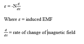
Recall if flux is constant, no emf is induced and the negative sign is linked to lenz’s law (direction of induced Emf).
Lenz’s Law: This law state that the direction of the induced current (or emf) is always such that it opposes the change in magnetic flux that produced it. For example;
If a flux is increasing through a coil, induced current creates a field opposing the increase and also if flux is decreasing, the induced current creates field reinforcing the original field.
Right-Hand Rule: The right-hand rule is a simple way to find direction of a magnetic force on a moving charge or current-carrying wire when you know the direction of the velocity (or current) and the magnetic field. Curl fingers are in the direction of the induced current and thumb points in the direction of the induced field that opposes the flux change.
How to use the Right-hand rule
i. Thump point to the direction of current (velocity of a positive charge)
ii. Index finger in the direction of magnetic field B
iii. Middle finger towards the direction of the magnetic force F
All three fingers are at right angles (3D coordinate system)
Lenz’s Law and practical Application
1. AC generators (Alternator): A coil rotates in a magnetic field, as the coil turns, the flux through it changes continuously hence, an alternating EMF is induced resulting to an alternating current (AC).
2. Induction Stove (Eddy-current heating): alternating current in a coil produces a changing magnetic field. This induces eddy currents in the metal pan, which heat it due to resistance.
3. Moving conductors in a magnetic field: A metal rod moving across a magnetic field has an emf induced along its length = Blv
Self-inductance and Mutal Inductance
Definition: Self-inductance (L) is the property of a coil (inductor) that opposes any change in the current flowing through it by inducing a “back emf” in the same coil. Self-inductance emf is expressed as; 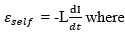
L = self-inductance (H)
Additional, when current increases, induced emf opposes the increase however, when current decreases, induced emf opposes the decrease. Large inductors e.g. solenoid store energy in the magnetic field. It is expressed as 
Mutual Inductance emf
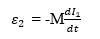
Definition: Mutual inductance M is the property of two nearby coils such that a changing current in one coil induces an emf in the other. If current I1 changes om coil 1, emf induced in coil 2. Similarly, a changing current in coil 2 induces emf in coil 1, with the same M.
Factors Affecting mutual inductance
i. Number of turns in each coil
ii. Distance between coil
iii. Orientation (alignment of axes)
iv. Core material (Iron core increases M)
Set up and Step down Transformers
Principle: Transformers work on mutual induction between two coils wound on a common iron core. An alternating current in the primary coil produces a changing magnetic flux that induced an alternating emf in the secondary coil. 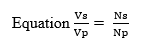
Where Vp = Primary voltage, Vs = Secondary voltage
Np = primary turns, Ns = secondary turns
Assuming no energy loss VpIp = VsIs. This means that higher voltage equal lower current and vice versa.
Step-up Transformer: A step-up transformer increases the output voltage compared to the input. It is used in power transmission to step up voltage for long-distance transmission (reducing power loss). Example of typical values; input 220v (primary) = output 11000 (secondary). Ns>Np =Vs>Vp.