ELECTROMOTIVE FORCE AND FARADAY’S LAW OF INDUCTION
| Site: | Newgate University Minna - Elearning Platform |
| Course: | General Physics II |
| Book: | ELECTROMOTIVE FORCE AND FARADAY’S LAW OF INDUCTION |
| Printed by: | Guest user |
| Date: | Monday, 2 November 2026, 11:45 PM |
1. EMF
Electromotive Force
The electromotive force, E of a cell is defined as the total work done in driving one coulomb of charge round a circuit.
Electromotive force is the energy per unit charge supplied by a source of electrical energy, such as a battery or a generator. It is not actually a force, but rather a potential difference between two points in an electric circuit. Electromotive force is measured in volts.
e.m.f = work/charge = W/Q
where W is measured in joules, Q in coulombs, e.m.f in volts. Hence
V = W/Q
or W = QV
Electromotive force can be used to describe the voltage supplied by a battery or generator, and it is related to the internal workings of these devices. For example, in a battery, the e.m.f is created by a chemical reaction that separates charges and creates a potential difference between the terminals of the battery. In a generator, the e.m.f is created by the relative motion between the magnetic field and a conductor.
4.1.1 Internal resistance
The internal resistance, r is the opposition to charge flow offered by the cell when it is discharging current to a circuit.
Internal resistance is the inherent resistance within an electrical source, such as a battery or generator, that opposes the flow of current in an electric circuit. It is caused by the resistance of the materials used to construct the source, as well as the resistance of the chemical reactions that occur within the source.
Internal resistance is important because it affects the output voltage and current of the source. As current flows through the source, it encounters resistance, which causes a voltage drop across the source. This reduces the output voltage and current of the source, and the amount of reduction depends on the internal resistance of the source.
4.1.2 Voltage drop
Voltage drop is the reduction in electrical potential that occurs when current flows through a component or conductor in an electric circuit. It is caused by the internal resistance of the component, which converts some of the electrical energy into heat. The voltage drop is proportional to the current flowing through the conductor and internal resistance of the conductor.
v = Ir
e.m.f = p.d across external resistance + p.d across internal resistance
E = V + v
Applying Ohms law, we have
E = IR + Ir
E = I (R+r)
I = E/(R+r)
4.1.3 Examples
1. A battery of e.m.f 24V and internal resistance 4Ω is connected to a resistor of 32Ω. What is the terminal p.d of the battery?
2. A cell of e.m.f 1.5V is connected in series with a resistor of resistance 3Ω. A high resistance voltmeter connected across the cell registers only 0.9V. Calculate the internal resistance of the cell.
3. An electric bell takes a current of 0.2A from a battery of two dry cells connected in series. Each cell has an e.m.f of 1.5V and an internal resistance of 1.0Ω.
(i) Calculate the effective resistance of the bell.
(ii) What current would the bells take if the cells were arranged in parallel?
4.2 Electrical Work Done in a Circuit
Work is done when charges flow from one point to another of different potential in a circuit. If Q coulombs of electricity flows between the two points whose differences in potential is V volts, then work done(W) is given by
W = QV
(joules = coulomb x volts)
The quantity of charges Q coulombs is given by
Q = It
where I is the current in amperes and t is time of flow of current in seconds
W = QV = IVt
W = IVt
(joules = amps x volt x seconds)
But from Ohms law, V = IR
W = QV = IVt = I x IR x t
= I2Rt
W = I2Rt
Substituting I = V/R
W = V2t/R
Magnetic Flux:
Magnetic Flux through a surface is the total number of magnetic field lines passing through it. If B = magnetic field strength, A = Area and = angle between the normal the surface:
= BACos
Unit = Weber(wb/m2)
Note Flux changes when; B changes (field strength varies), A changes (loops size and shape), and changes (loops rotate in the field)
2. Faraday’s law of Electromagnetic Induction
The law state that whenever the magnetic flux linked with a circuit changes, an electromotive force (EMF) is induced in the circuit.
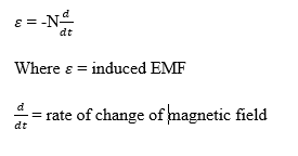
Recall if flux is constant, no emf is induced and the negative sign is linked to lenz’s law (direction of induced Emf).
Lenz’s Law: This law state that the direction of the induced current (or emf) is always such that it opposes the change in magnetic flux that produced it. For example;
If a flux is increasing through a coil, induced current creates a field opposing the increase and also if flux is decreasing, the induced current creates field reinforcing the original field.
Right-Hand Rule: The right-hand rule is a simple way to find direction of a magnetic force on a moving charge or current-carrying wire when you know the direction of the velocity (or current) and the magnetic field. Curl fingers are in the direction of the induced current and thumb points in the direction of the induced field that opposes the flux change.
How to use the Right-hand rule
i. Thump point to the direction of current (velocity of a positive charge)
ii. Index finger in the direction of magnetic field B
iii. Middle finger towards the direction of the magnetic force F
All three fingers are at right angles (3D coordinate system)
Lenz’s Law and practical Application
1. AC generators (Alternator): A coil rotates in a magnetic field, as the coil turns, the flux through it changes continuously hence, an alternating EMF is induced resulting to an alternating current (AC).
2. Induction Stove (Eddy-current heating): alternating current in a coil produces a changing magnetic field. This induces eddy currents in the metal pan, which heat it due to resistance.
3. Moving conductors in a magnetic field: A metal rod moving across a magnetic field has an emf induced along its length = Blv
Self-inductance and Mutal Inductance
Definition: Self-inductance (L) is the property of a coil (inductor) that opposes any change in the current flowing through it by inducing a “back emf” in the same coil. Self-inductance emf is expressed as; 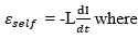
L = self-inductance (H)
Additional, when current increases, induced emf opposes the increase however, when current decreases, induced emf opposes the decrease. Large inductors e.g. solenoid store energy in the magnetic field. It is expressed as 
Mutual Inductance emf
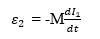
Definition: Mutual inductance M is the property of two nearby coils such that a changing current in one coil induces an emf in the other. If current I1 changes om coil 1, emf induced in coil 2. Similarly, a changing current in coil 2 induces emf in coil 1, with the same M.
Factors Affecting mutual inductance
i. Number of turns in each coil
ii. Distance between coil
iii. Orientation (alignment of axes)
iv. Core material (Iron core increases M)
Set up and Step down Transformers
Principle: Transformers work on mutual induction between two coils wound on a common iron core. An alternating current in the primary coil produces a changing magnetic flux that induced an alternating emf in the secondary coil. 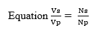
Where Vp = Primary voltage, Vs = Secondary voltage
Np = primary turns, Ns = secondary turns
Assuming no energy loss VpIp = VsIs. This means that higher voltage equal lower current and vice versa.
Step-up Transformer: A step-up transformer increases the output voltage compared to the input. It is used in power transmission to step up voltage for long-distance transmission (reducing power loss). Example of typical values; input 220v (primary) = output 11000 (secondary). Ns>Np =Vs>Vp.