MODULE1: ELECTROSTATIC
| Site: | Newgate University Minna - Elearning Platform |
| Course: | General Physics II |
| Book: | MODULE1: ELECTROSTATIC |
| Printed by: | Guest user |
| Date: | Monday, 2 November 2026, 11:46 PM |
Description
These Course will help students understand the fundamental principles of electric current and apply them in real-life situations, including electronics, and how to go about them.
1. INTRODUCTION
1.0 Introduction to Electricity
Electricity is a form of energy associated with the presence and motion of electric charge. It is used for powering homes and industries, Lighting and heating, Communication systems, Transportation and for medical equipment. The scientific study of electricity and its applications is known as electrical engineering and electromagnetism. Understanding electric charge and electrical principles is crucial for designing safe, efficient, and reliable electrical systems. Electricity exists mainly in two forms:
i. Static electricity: Electric charges at rest, often produced by friction or induction.
ii. Current electricity: The continuous flow of electric charge through a conductor.
1.2 Electrostatic
Electrostatics also called Static Electricity, is a branch of physics that deals with the study of electric charges at rest and the forces, fields, and potentials associated with them.
In electrostatics, charges do not flow continuously as they do in electric circuits. Instead, they remain stationary or accumulate on the surfaces of materials. This area of physics explains phenomena such as attraction and repulsion between charged bodies, lightning and static shocks. Examples of static electricity include the followings;
- Rubbing a balloon on dry hair: The balloon attracts hair strands and may stick to a wall due to accumulated electric charges.
- Clothes sticking together after drying: Especially synthetic clothes in a dryer; this happens because of charge buildup.
- Small electric shock when touching a metal object: For example, touching a door handle after walking on a carpet.
- Lightning: A large-scale natural example of static electricity discharge between clouds or between a cloud and the ground.
- Dust sticking to TV or computer screens: Static charges attract light dust particles.
- Photocopiers and laser printers: They use static electricity to attract toner powder to paper.
- Plastic comb attracting pieces of paper: After rubbing the comb on dry hair or wool.
- Hair standing up when removing a sweater: Caused by transfer of electric charges.
- Fuel tankers trailing metal chains: Used to discharge static electricity and prevent sparks.
- Electrostatic spray painting: Paint particles are electrically charged to stick evenly to surfaces.
1.3 Production of Electric Charges
Electric charges can be produced by the following methods:
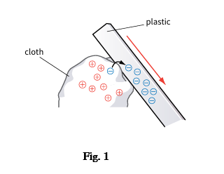
1. Charging by Friction: When two different materials are rubbed together, see Fig1., electrons may be transferred from one material to another. This results in one object becoming positively charged and the other negatively charged. Example: Rubbing a balloon against dry hair causes the balloon to stick to a wall.
2. Charging by Conduction: Charging by conduction occurs when a charged object is brought into direct contact with a neutral conductor. Electrons flow between the objects until charge is redistributed. Example: Touching a charged rod with a metal sphere transfers charge to the sphere.
3. Charging by Induction: Charging by induction occurs without direct contact. When a charged object is brought near a neutral conductor, charges within the conductor rearrange themselves. If the conductor is grounded, it can acquire a net charge. Example: Bringing a charged rod near a metal sphere causes separation of charges within the sphere.
4. Electrostatic Discharge: When a large amount of charge accumulates on an object, it may suddenly discharge in the form of a spark or shock. Examples: - Lightning - Electric shock after walking on a carpet and touching a metal object.
1.3.1 Conservation of Electric Charge
The law of conservation of charge states that: The total electric charge in an isolated system remains constant.
Charge cannot be created or destroyed; it can only be transferred from one body to another.
Example: When two objects are rubbed together, electrons move from one object to the other. One becomes positively charged and the other negatively charged, but the total charge remains unchanged.
1.4 Coulomb’s Law of Electrostatics and superposition Principle
1.4.1 Coulomb’s law
Coulomb’s law describes the electrostatic force between two-point charges. The superposition principle allows calculating net forces or fields from multiple charges by vector addition.
Coulombs law state that; the magnitude of the electrostatic force between two-point charges is directly proportional to the product of their charges and inversely proportional to the square of the distance between them. Mathematically expressed. 
Where:
F = electrostatic force (N)
Q1 and Q2 = magnitudes of the charges (C)
R = distance between the charges (M)
K = Coulomb’s constant (9.0 x N.m2/C2)
Note: The force is Attractive for unlike charges and Repulsive for like charges.
Work examples:
1. An electron is at a distance of 5.0x m away from the center of the proton. Calculate the electrostatic force on it.?
2. A point charge of +3.0× C is 12.0cm distant from a second point charge of −1.50× C. Calculate the magnitude of the force on each charge.
3. What must be the distance between point charge q1=26.0µC and point charge q2= 47.0µC for the electrostatic force between them to have a magnitude of 5.70N.
1.3.1 Conservation of Electric Charge
The law of conservation of charge states that: The total electric charge in an isolated system remains constant.
Charge cannot be created or destroyed; it can only be transferred from one body to another.
Example: When two objects are rubbed together, electrons move from one object to the other. One becomes positively charged and the other negatively charged, but the total charge remains unchanged.
2. COULOMB’S LAW OF ELECTROSTATICS AND SUPERPOSITION PRINCIPLE
1.4 Coulomb’s Law of Electrostatics and superposition Principle
1.4.1 Coulomb’s law
Coulomb’s law describes the electrostatic force between two-point charges. The superposition principle allows calculating net forces or fields from multiple charges by vector addition.
Coulombs law state that; the magnitude of the electrostatic force between two-point charges is directly proportional to the product of their charges and inversely proportional to the square of the distance between them. Mathematically expressed F =
Where:
F = electrostatic force (N)
Q1 and Q2 = magnitudes of the charges (C)
R = distance between the charges (M)
K = Coulomb’s constant (9.0 x N.m2/C2)
Note: The force is Attractive for unlike charges and Repulsive for like charges.
Work examples:
1. An electron is at a distance of 5.0x m away from the center of the proton. Calculate the electrostatic force on it.?
2. A point charge of +3.0× C is 12.0cm distant from a second point charge of −1.50× C. Calculate the magnitude of the force on each charge.
3. What must be the distance between point charge q1=26.0µC and point charge q2= 47.0µC for the electrostatic force between them to have a magnitude of 5.70N
1.4.2 Superposition Principle
Superposition Principle State that for multiple charges, the net force on any charge is the vector sum of forces from each charge individually. It is given as Fnet = . Similarly, they can superpose while potentials add scalarly:
The linearity systems from Maxwell’s equations and simplifies complex systems as see in prior Gauss’s law discussion for symmetric fields.
Example calculations
1. A circuit consist of two DC voltage sources of 12V and 6V connected in series with the resistor of 6ohm. Using the superposition principle determine the current following through the resistor
2. A resistor of 4ohm is connected to a pair current source supplying current of 5A and 3A respectively in the same direction. Calculate the superpose voltage across the resistor.
3. Two voltage sources of 10V and 4V are connected in opposite directions across a 2ohm resistor. Calculate the net current in the circuit.
4. A circuit contains a 20V voltage source and an 8V voltage connected with 4ohm resistor. Determine the current contributed by each source and hence calculate the total current in the resistor.
5. In a certain electrical circuit, a 15V sources and a 5V source are connected in different directions across a 5ohm resistor.
6. Determine a 3ohm resistor connected in a circuit containing two voltage sources of 9V and 3V.
7. Two current sources of 2A and 6A are connected to a 5ohm resistor.
1.5 Electric Field
A charged object experiences a force in an electric field. This is what an electric field is. We say that there is an electric field anywhere an electric charge experiences a force. An electric field is a field of force.
An electric field is a region of sp ace around a charged particle or object in which another electric charge experiences an electric force.
Electric Field Strength at a point is defined as the electric force per unit positive test charge at a point in the field. E =
Where:
E = electric field strength (N C⁻¹ or V m⁻¹)
F = electric force N
Q = test charge (C)
The electric field is a vector quantity, meaning it has both magnitude and direction.
The direction of the electric field at any point is the direction of the force acting on a positive test charge placed at that point.
1.6 Potential
Potential difference (p.d.), also called voltage, is the work done or energy transferred per unit charge in moving a charge between two points in an electric circuit. V = W / Q
Where: -
V = potential difference (V)
W = work done or energy transferred(J)
Q = charge (C)
1.7 Gauss’s Law and applications
Gauss’s law is a fundamental principle in electromagnetism that relates electric flux through a closed surface to the enclosed electric charge. It simplifies calculations for symmetric charges distributions.
1.7.1 Gauss’s Law
This law state that the total electric flux through any closed surface (Gaussian Surface) equals the net charge (Qenc.) enclosed divided by the permittivity of Free space.
5.7.2 Applications of Gauss’s law
Gauss’s law excels for symmetric charge distributions, deriving fields without direct integration; This case derived Coulomb’s law and explain shielding e.g. Faraday cage
1. Spherical symmetry: For instance, in a charge sphere, inside a uniformly charged hollow sphere E is zero; outside E, matches a point charge at the center.
2. Cylindrical symmetry: For instance, infinite line charge
3. Planar Symmetry: e.g. Infinite sheet, charge density
4. Conductors: here field inside is zero; surface charge creates field only inside
3. CAPACITANCE AND ENERGY STORED IN ELECTRIC FIELDS
2.0 Capacitance
Capacitance is a measure of the ability of a capacitor to store electric charge. It is defined as the ratio of the charge stored on either plate to the potential difference across the plates.
C = Q / V
Unit: Farad. Furthermore, Farad is large, so in practice capacitance is usually in Microfarads, nano farads and picofarads.
2.1 Capacitor Geometry:
A parallel plate capacitor in air or vacuum it is expressed as: 
Where: A = area of one plate
D = distance between plates
permittivity of free space (8.85x )
If an insulating material (Dielectric) with dielectric constant K fills the space between the plates; 
This means that the capacitor stores more charge at the same voltage.
Energy store in a capacitor
2.3 Capacitors
A capacitor is an electrical component used to store electrical energy in an electric field.
It consists of two conducting plates separated by an insulating material called a dielectric (e.g. air, paper, mica, ceramic).

2.3.1 Working Principle
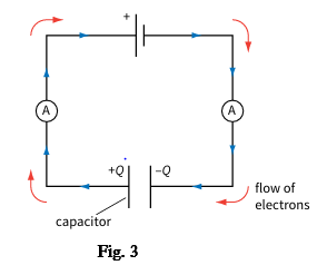
i. When a voltage is applied across the plates, an electric field is set up between them.
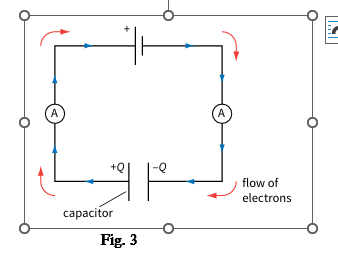
ii. Equal and opposite charges accumulate on the plates, and energy is stored in the electric field.
2.4 Arrangement of Capacitors
Capacitors in circuits are primarily arranged in series and parallel configurations, each altering total capacitance, voltage and charge differently.
1. Capacitors in series
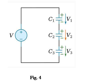
i. Have same charges (Q) on all capacitor i.e Q = Q1 = Q2 = Q3
ii. The total voltage is shared i.e. V = v1+v2 +v3
iii. The equivalent capacitance decreases 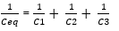
iv. Total capacitance is less than the smallest capacitance
v. Use when higher working voltage is needed.
2.4 Arrangement of Capacitors
Capacitors in circuits are primarily arranged in series and parallel configurations, each altering total capacitance, voltage and charge differently.
1. Capacitors in series
i. Have same charges (Q) on all capacitor i.e Q = Q1 = Q2 = Q3
ii. The total voltage is shared i.e. V = v1+v2 +v3
iii. The equivalent capacitance decreases 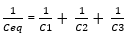
iv. Total capacitance is less than the smallest capacitance
v. Use when higher working voltage is needed.
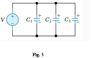
2.Capacitors in Parallel
i. The voltage across each capacitor is the same i.e. V = V1 = V2 = V3
ii. The equivalent capacitance increases Ceq = C1+C2+C3
iii. The total charge is the sum of the individual charge Q = Q1+Q2+Q3
iv. Parallel combinations are used to increase energy and charge storage
v. Parallel capacitance stores more charge hence total capacitance increases