
ASSEMBLY LANGUAGE
Have you ever thought about how a computer knows what to do when you click a button or play a game? The CPU (Central Processing Unit) is a little brain that tells your computer what to do step by step. The CPU does not know how to read conventional words; it only knows how to read special codes. This is where assembly language comes in. People can talk to the computer's brain in a hidden language called Assembly. They do this by using short, basic terms like ADD (add numbers) or JMP (jump to a different command). These instructions tell the computer exactly what to do and how to do it, and it does it very quickly and accurately. The CPU employs small storage areas called registers to follow these steps. These are very rapid places where the computer stores numbers or information as it works on a task.
1. ASSEMBLY LANGUAGE
ASSEMBLY LANGUAGE
4.0 INTRODUCTION
Have you ever thought about how a computer knows what to do when you click a button or play a game? The CPU (Central Processing Unit) is a little brain that tells your computer what to do step by step. The CPU does not know how to read conventional words; it only knows how to read special codes. This is where assembly language comes in. People can talk to the computer's brain in a hidden language called Assembly. They do this by using short, basic terms like ADD (add numbers) or JMP (jump to a different command). These instructions tell the computer exactly what to do and how to do it, and it does it very quickly and accurately. The CPU employs small storage areas called registers to follow these steps. These are very rapid places where the computer stores numbers or information as it works on a task.
4.1 ASSEMBLY LANGUAGE
Assembly language Is essential building block for how computers execute instructions at the hardware level. Assembly language is a low-level programming language that act as a crucial bridge between the codes we write and the machine code that the computer hardware understands. Unlike the high-level language such as java, python and ruby which are designed and are much easier for human to write, read and understand, Assembly language program is much closer to the computer hardware. this gives programmers direct control over the CPU and memory, allowing them to optimize how the machine performs tasks. Each instruction in assembly language tells the computer to perform a very specific operation like moving data between registers, performing arithmetic or jumping into new instruction. Because of its precision, Assembly language is used in areas where performance and control are critical; such as embedded systems, game console, device drivers, and even operating system. Although, it might be challenging to learn, understanding assembly gives you deep insight on how computers work at their core.
4.2 BASIC COMPONENTS OF ASSEMBLY
Assembly language are the building blocks that allows you to communicate directly with the computer hardware. These are
i. INSTRUCTIONS: which tells the computer which action to perform.
ii. OPERANDS: which specifies the data the instruction will work on.
Assembly language uses Mnemonics i.e human readable abbreviations like MOV (move), ADD (addition), JMP (Jump), to represent instructions. Each instruction operates in registers (which are small fast storage area inside the CPU where data is temporarily held during operations). It is important to know that the Assembly syntax depend on the architecture of the device you are programming, which means codes written for one type of CPU like X86 will not work for another CPU such as R. together these components give programmers fine-tuned control over how computers handle tasks, allowing efficient and precise execution of instructions.
4.3 CPU REGISTERS
CPU registers are small high speed storage location within the processor that holds data and instruction temporarily computation. They play a crucial role in the execution of a program; as they provide the fastest means for the CPU to access and manipulate data. There are different types of registers, each design for specific purposes such as:
i. General-Purpose Register: holds data for various operations
ii. Specific- Purpose Register: they are like instruction register which holds current instruction being executed in the program counter and which keep tracks of the address for the next instruction in status register.
iii. Status Register maintain information about the current state of the CPU including flags of the arithmetic operations. For example, consider a simple operation where you want to add 2 nos. The CPU might first load the no (A) into a general-purpose register and the second no (B) into another general-purpose register. The addition operation is then perform using these registers with the result stored in a third register (C). this use of registers allows the CPU to perform calculations rapidly significantly enhancing the overall performance.
4.4 FLAGS IN ASSEMBLY
Flags are special bits in the CPU that stores the results of operations and help controls the flow of program. The status flags are updated automatically based on the outcome of instructions and are used to make decisions during execution. For example;
i. the zero (O) flag is set when the result of an operation is zero (ZE) while
ii. the Carry flag (CF) is set if an arithmetic operation produces a result too large for the register to hold.
iii. The overflow flag (OF) tracks whether an arithmetic operation results in an overflow
iv. The Sign flag (SF) indicate whether the result is negative.
Flags are specifically important in conditional operations; for instance: after a comparison, a jump instruction will check the status of the flag to determine whether or not to jump to another part of the code. Understanding flags is key to controlling how the CPU processes tasks and reacts to different outcomes in assembly programming.
4.5 MEMORY AND ADDRESSING MODES
Memory and addressing modes are the key concepts in assembly language that helps us understand how data is stored and accessed in a computer memory.
Memory refers to the physical location where data is kept, allowing programs to retrieve and manipulate information.
Addressing modes defines the different ways we can access this memory, determining how the CPU interpret the addresses in instructions. This demonstrates how addressing modes helps us efficiently access and manage data in memory while programming. Common addressing modes include:
I. Immediate addressing e.g ADD R1, 5 which add the value 5 directly to register R1.
II. Direct addressing: the instruction could be ADD R1, [1000]; where 1000 is the memory address containing the value to be added to R1.
III. Indirect addressing: you might see ADD R1, [R2]; where register R2 holds the address of the value to be added to R1.
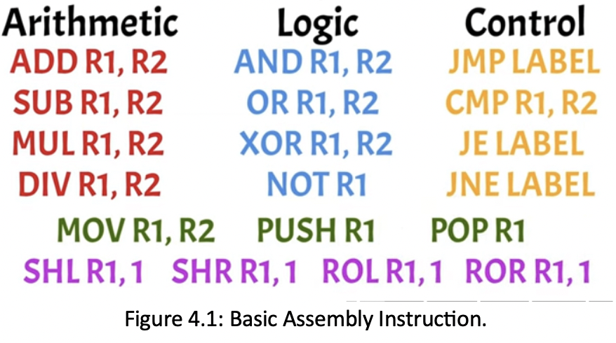
4.6 BASIC ASSEMBLY INSTRUCTION
Basic assembly instructions fall into several categories, each serving a unique function in programming
1. Arithmetic Instructions perform mathematical operation such as:
ADD R1, R2: adds the value in register R2 to R1;
SUB R1, R2: subtracts R2 FROM R1;
MUL R1, R2 and DIV R1, R2 instructions performs multiplication and division respectively.
2. Logic Instruction handles bitwise operations:
AND R1, R2 performs a bitwise AND where only bits that are 1 in both R1 and R2 remain 1;
OR R1, R2 performs a bitwise OR setting bits to 1 if either register has a 1;
XOR (Exclusive OR): XOR R1, R2 performs and XOR resulting in 1 if the bits differ.;
The NOT instruction alternates the bits in a register, changing 1s to 0s and vice versa.
3. Control Instructions direct program flows:
JMP (Jump) label cause the program to jump a specific point labelled in the code;
CMP (Compare) R1, R2 compares the values in R1 and R2. Based on this comparison, JE label (Jump Equal) if the values are equal;
JNE label (Jump Not Equal) if they are not;
Data movement instruction transfer data; MOV R1, R2: Moves data from R2 to R1;
PSH (PUSH) R1; saves R1’s value onto the stack;
POP R1 retrieves the last value from the stack.
4. Bit manipulation instruction include:
SHL (Shift Left): shifts register’s bit left, essentially multiplying the value by 2 (SHL R1, 1);
SHR (Shift Right): Shifts right, dividing the value by 2 (SHR R1,1);
ROL (ROTATE LEFT) and ROR (ROTATE RIGHT) rotates bits left or right (i.e, ROL 1, 1 and ROR 1, 1) Looping them around.
These instructions allow precise control over data, arithmetic and program flow in assembly programming as shown in figure 4.1. Keep in mind that there are even more instructions available in Assembly providing further capabilities for developers.
4.6 HOW ASSEMBLY IS EXECUTED
Assembly language is executed through a process known as the fetchDecodeExecute cycle which is fundamental to how a CPU operates. This cycle consists of three main stages:
• FETCHING: In this stage, the CPU retrieves an instruction from the memory, typically pointed to by the program counter. For instance, if the instruction is SHL R1, the CPU fetches this command from memory.
• DECODING: In this stage, the CPU interpret the fetched instruction, determining what action is required and identifying the involved operands such as recognizing that it needs to shift the bits in R1, to the left by 1 position.
• EXECUTE: In this stage, the CPU carries out the operation as specified by the instruction. From our example, it shifts the bits of R1 left, effectively multiplying the value by 2. The cycle repeats for each program, allowing the CPU to process commands sequentially whether they involve arithmetic calculation, logical operations or controlling instructions. By understanding this cycle, we see how assembly language directly translates into actions performed by the computer’s hardware, connecting human-readable code to machine-level execution.
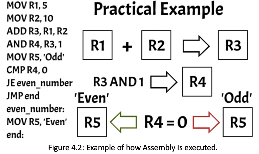
4.7 PRACTICAL EXAMPLE
MOV R1, 5
MOV R2, 10
ADD R3, R1, R2
AND R4, R3, 1
MOV R5, ‘Odd’
CMP R4, 0
JE Even_Number
JMP End
Even_number
MOV R5, ‘Even’
End
In assembly code, we start by coding the values 5 and 10 into registers R1 and R2 respectively. The ADD instruction then combine these two values and stores the result in register R3. To determine whether the result is even or odd, we perform a bitwise AND operation with 1 and sore the outcome in R4. The AND operation effectively checks the least significant bit of the sum:
If its 0, the number is Even;
If its 1, the number is Odd
Initially, we assume the result is ‘Odd’ by loading this string into the register R5. We then compare R4 to 0;
if they are equal, it indicates that the sum is Even and the program Jumps to the Even_number label to update R5 with string ‘Even’.
If the sum is ‘Odd’, the program skips this step and jumps directly to the ‘End’ label as shown in Figure 4.2.
4.8 REAL WORLD APPLICATION
Assembly language may be low-level language compare to modern programming languages like Python, Ruby and Java, but it plays a vital role in many real-world applications where performance and precise control over hardware are crucial. For example, it is commonly used in embedded systems, like those found in cars, medical devices, household appliances where efficiency and direct control over hardware resources are essential. Game consoles, and graphics program also utilizes assembly for optimizing performance in making the most out of hardware capabilities.
Additionally, assembly is critical in device drivers which act as the interfaces between hardware and the operating system (OS). Even parts of OP themselves especially those that need to interact directly with hardware are often written in assembly. By using assembly, developers can fine-tune programs to run as efficiently as possible which is particularly vital resource-constrained environments or performance-critical tasks.
4.9 LIMITATIONS OF ASSEMBLY
While assembly language offers significant advantages in terms of performance and control over the hardware, it also comes with notable limitations. One of the major drawbacks is its complexity and verbosity; writing code in assembly requires a deep understanding of the underlying hardware architecture which could be daunting for many programmers. This complexity leads to longer development times, as even simple tasks can require extensive lines of codes compared to high-level languages.
Assembly language is not portable; codes written for one architecture typically cannot run in another without significant modifications. This lack of portability makes assembly less suitable for large-scale software development where flexibility and maintainability are essential.
Assembly language lacks the rich libraries and built-in features available in high-level languages limiting it use in modern software applications. Overall, while assembly is powerful for specific tasks, its limitations can hinder productivity and adaptability in the fast-paced world of software development.