
TCP/IP PROTOCOL SUITE
The OSI model came after the development of the TCPIIP protocol suite. As a result, the OSI model's layers and those in the TCP/IP protocol suite do not precisely correspond. The host-to-network, internet, transport, and application layers comprised the original TCP/IP protocol suite. On the other hand, the host-to-network layer is comparable to the sum of the physical and data link layers when comparing TCP/IP to OSI. The application layer essentially performs the functions of the session, presentation, and application layers, while the transport layer in TCP/IP handles some of the session layer's responsibilities. The internet layer is comparable to the network layer.
1. TCP/IP PROTOCOL
TCP/IP PROTOCOL SUITE
4.0 INTRODUCTION
The OSI model came after the development of the TCPIIP protocol suite. As a result, the OSI model's layers and those in the TCP/IP protocol suite do not precisely correspond. The host-to-network, internet, transport, and application layers comprised the original TCP/IP protocol suite. On the other hand, the host-to-network layer is comparable to the sum of the physical and data link layers when comparing TCP/IP to OSI. The application layer essentially performs the functions of the session, presentation, and application layers, while the transport layer in TCP/IP handles some of the session layer's responsibilities. The internet layer is comparable to the network layer.
4.1 TCP/IP PROTOCOL
The interactive modules that make up the hierarchical TCP/IP protocol each have a distinct role, albeit they are not always dependent on one another. The layers of the TCP/IP protocol suite contain comparatively independent protocols that can be mixed and matched based on the requirements of the system, in contrast to the OSI model, which outlines which functions belong to each of its layers as depicted in Figure 4.1. The word "hierarchical" refers to the fact that one or more lower-level protocols support each upper-level protocol. Three protocols are defined by TCP/IP at the transport layer: Stream Control Transmission Protocol (SCTP), User Datagram Protocol (UDP), and Transmission Control Protocol (TCP). The Internetworking Protocol (IP) is the primary protocol defined by TCP/IP at the network layer; additional protocols that facilitate data flow are also included.
1. Host-to-Network Layer: The TCP/IP reference model simply notes that in order for the host to deliver IP packets to the network, it must establish a connection with the network via a protocol. It is an undefined protocol that differs from network to network and host to host.
2. Internet Layer: Its function is to enable hosts to introduce packets into any network and allow them to go autonomously to their destination, which may be on an alternative network. If in-order delivery is needed, higher levels are responsible for rearranging them if they arrive in a different order than when they were sent. IP (Internet Protocol) is the official packet format and protocol defined by the internet layer. Delivering IP packets to their intended location is the responsibility of the internet layer. Here, avoiding congestion and packet routing are undoubtedly the main concerns.
3. The Transport Layer: The transport layer is the layer that sits above the internet layer in the TCP/IP paradigm. Like the OSI transport layer, its purpose is to enable peer entities on the source and destination hosts to have a communication. This article defines two end-to-end transport protocols. A byte stream that originates on one computer can be transferred error-free to any other computer connected to the internet thanks to the first one, TCP (Transmission Control Protocol), a dependable connection-oriented protocol. It separates each individual message from the incoming byte stream before sending them all to the internet layer. The receiving TCP process reassembles the received messages into the output stream at the destination. In order to prevent a fast sender from overloading a slow receiver with more messages than it can process, TCP also manages flow control. UDP (User Datagram Protocol), the second protocol in this layer, is an unreliable, connectionless protocol for applications that want to provide their own sequencing and flow control instead than relying on TCP's. It is also frequently used for one-shot, client-server request-reply queries and applications like speech or video transmission where speedy delivery is more crucial than precise delivery.
4. The Application Layer: There are no session or presentation layers in the TCP/IP paradigm. The application layer sits on top of the transport layer. It includes every higher-level protocol. Among the earliest were electronic mail (SMTP), file transfer (FTP), and virtual terminal (TELNET). A user on one machine can log on to a remote machine and operate there thanks to the virtual terminal protocol. The file transfer protocol offers a method for effectively transferring data between computers. Initially merely a file transmission, electronic mail eventually evolved a specific protocol (SMTP). Over time, numerous other protocols have been added to these, including HTTP, which is used to retrieve pages on the World Wide Web, NNTP, which is used to move USENET news articles around, and the Domain Name System (DNS), which maps host names onto their network addresses.
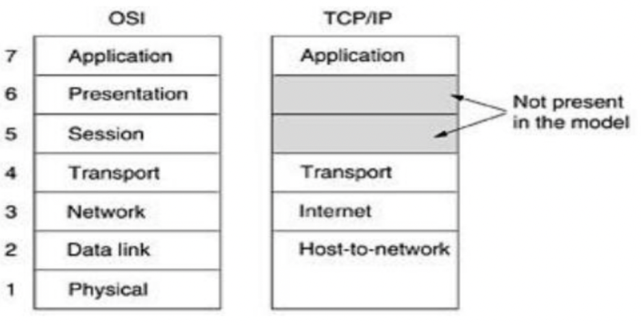
Figure 4.1: Differences between OSI and TCP/IP Reference Model
4.1 OSI AND TCP/IP REFERENCE MODEL COMPARISON
There are several similarities between the OSI and TCP/IP reference models. The idea of a stack of separate protocols is the foundation of both. Additionally, the layers' functions are rather comparable. For instance, the purpose of the layers in both models up to and including the transport layer is to give processes that want to communicate an end-to-end, network-independent transport service. Together, these layers make up the transport provider. The layers above transport in both models are once again application-focused customers of the transport service. Even with these basic parallels, there are a lot of variances between the two models. The OSI model is based on three key ideas:
1. Services.
2. User interfaces.
3. Protocols.
The OSI model's ability to clearly distinguish between these three ideas is likely its greatest contribution. Every layer serves the layer above it in some way. The service specification describes the function of the layer, not how it functions or how entities above it access it. It establishes the semantics of the layer.
The interface of a layer instructs the processes above it on how to use it. It outlines the parameters and the anticipated outcomes. Furthermore, it makes no mention of the inner workings of the layer. Last but not least, a layer's peer protocols are its own concern. As long as it completes the task (i.e., delivers the available services), it is free to employ whichever protocols it desires. Additionally, it can alter them at will without compromising higher-layer software. Despite attempts to modify the TCP/IP model after the fact to make it more OSI-like, it did not initially distinguish between service, interface, and protocol. For instance, the internet layer only provides SEND IP PACKET and RECEIVE IP PACKET as actual services.
Because of this, the OSI model's protocols are more concealable than those in the TCP/IP model and are more easily interchangeable as technology advances. One of the primary goals of having layered protocols in the first place is the ability to make such modifications. The development of the related protocols came after the creation of the OSI reference model. Because of this ordering, the model was rather broad and was not biased toward any one set of procedures. This ordering's drawback is that the designers lacked subject-matter expertise and were unsure of which functionality to include in which layer.
Another distinction is between connection-oriented and connectionless communication. Connection-oriented communication is the only one that matters in the transport layer, where users can see the transport service, however the OSI model permits both connectionless and connection-oriented communication in the network layer. Users have a choice because the TCP/IP paradigm enables both modes in the transport layer but only offers one mode (connectionless) in the network layer. This decision is particularly crucial for basic R/R techniques.
4.2 INTRANET AND INTERNET PROTOCOL ADDRESS
4.3.1 Intranet Protocol Address
An Intranet Protocol (IP) Address is a distinct numerical identifier allocated to each device linked to a private network (intranet). It facilitates communication among computers, servers, printers, and other networked devices within an enterprise. In contrast to public IP addresses that facilitate access to the global internet, intranet IP addresses operate just within a confined network. Comprehending intranet IP addresses is crucial for students pursuing networking, system administration, and cybersecurity, as they underpin local network communication and management.
What is an Intranet?
An intranet is a private network utilized by
a company for resource sharing, communication, and safe data storage. It is not
reachable via the public internet and is typically utilized in corporate
settings, academic institutions, governmental bodies, and healthcare
facilities. An intranet has key feature such as:
•
Confidential and Secure: Access is restricted
to approved individuals.
•
Resource Sharing: Facilitates the
distribution of files, printers, and programs.
•
Communication and Collaboration: Facilitates
internal email, messaging, and project management applications.
•
Employs IP Addressing: Devices within the
intranet utilize private IP addresses for communication.
What is an Intranet Protocol (IP) Address?
An Intranet IP Address is a distinct, private identity allocated to each device within an internal network, facilitating communication among devices while safeguarding them from external internet threats. An Intranet IP Address keeps internal communications safe from external attacks; allows seamless interaction between devices in an organization; enables efficient allocation of resources such as printers, servers, and storage; and reduces the need for multiple public IP addresses.
However,
complications exist in intranet protocol addressing, such as the assignment of
identical IP addresses to two devices, resulting in connectivity
problems; Inefficient IP allocation might impede network
performance; Unauthorized devices may seek to access the intranet.
fortunately, these could be addressed through:
1. ensuring of appropriate IP address distribution in order to avoid conflicts.
2. Establish VLANs (Virtual Local Area Networks): Classifies gadgets into coherent categories for enhanced traffic regulation.
3. Augment security protocols by Implementing firewalls, access control lists (ACLs), and authentication systems.
Therefore, Intranet IP addresses are essential for the effective and secure operation of private networks. They provide communication between businesses while ensuring security and control over networked equipment. Comprehending the mechanics of intranet IP addressing is essential for students aspiring to professions in networking, cybersecurity, and IT administration. Through proficient management of IP addresses, firms may optimize network performance, bolster security, and provide uninterrupted operations.
Types of IP Addresses in an Intranet
- Static IP Address – Manually assigned and does not change. Commonly used for servers and printers.
- Dynamic IP Address – Assigned automatically by a Dynamic Host Configuration Protocol (DHCP) server. Common for employee computers and mobile devices.
Private IP Address Ranges
In intranet networks, the Internet Assigned Numbers Authority (IANA) reserves private IP address ranges for local usage. The internet cannot route these addresses. Example of an Intranet IP Address: 192.168.1.10. There are three major private IP address ranges and these are:
1. Class A (10.0.0.0 – 10.255.255.255)
- Supports large networks (up to 16 million devices).
- Used by multinational corporations and large organizations.
2. Class B (172.16.0.0 – 172.31.255.255)
- Supports medium-sized networks (up to 65,000 devices).
- Used by universities and medium-sized businesses.
3. Class C (192.168.0.0 – 192.168.255.255)
How Intranet IP Addresses Work
Step-by-Step Process of IP Addressing in an Intranet:
- Device Connection: When a device connects to the network, it requests an IP address.
- IP Assignment: The DHCP server assigns an available private IP address.
- Communication Setup: The device uses its assigned IP to send/receive data within the intranet.
- Routing & Switching: Routers and switches direct the data to the correct destination using IP addresses.
- Network Security: Firewalls and access controls ensure only authorized devices communicate within the intranet.
To check your intranet IP address on different operating systems:
- Windows: Open Command Prompt and type →
ipconfig - Mac: Open Terminal and type →
ifconfig | grep inet - Linux: Open Terminal and type →
hostname -I
The result will show your private IP address assigned within the intranet.
4.3.2 Internet IP Protocol Address
IP Address or Network address or logical address
An IPv4
address is a 32-bit identifier that uniquely and universally designates a
device's connection, such as a computer or router, to the Internet. IPv4
addresses are distinctive. Each address is distinctive in that it establishes a
singular, exclusive connection to the Internet. Two machines on the Internet
cannot possess identical addresses simultaneously. IPv4 addresses are
ubiquitous, as the addressing system must be recognized by any host seeking to
connect to the Internet.
An address space is defined by a protocol like IPv4 that specifies
addresses. An address space refers to the entirety of addresses utilized by the
protocol. If a protocol employs N bits to specify an address, the address space
is 2^N, as each bit can assume two distinct values (0 or 1), resulting in 2^N
possible combinations for N bits. IPv4 use 32-bit addresses, resulting in an
address space of 2^32 or 4,294,967,296 (exceeding 4 billion). Theoretically, in
the absence of limitations, over 4 billion devices could connect to the
Internet.
Two common
notations for representing an IPv4 address are binary notation and dotted
decimal notation.
Binary Representation
The IPv4
address is represented in binary format as 32 bits. Each octet is commonly
designated as a byte. An IPv4 address is commonly referred to as a 32-bit
address or a 4-byte address. An illustration of an IPv4 address in binary
format is as follows:
01110101 10010101 00011101 00000010
Dotted Decimal Notation
IPv4 addresses are typically expressed in decimal format, with a decimal point between the bytes for enhanced compactness and readability. The subsequent representation of the aforementioned address is in dotted decimal notation:
117.149.29.2
Figure 4.2 illustrates an IPv4 address in both binary and dotted-decimal
formats. Each byte (octet) consists of 8 bits, hence each number in
dotted-decimal notation ranges from 0 to 255.
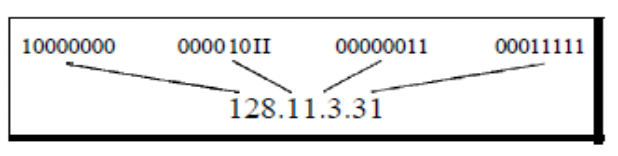
Figure 4.2: Dotted-decimal notation and binary notation for an IPv4 address
IP Address Classes
The first framework of IPv4 addressing utilized the classification system. This architecture is referred to as classful addressing. Classful addressing categorizes the address space into five distinct classes: A, B, C, D, and E. Each class occupies a portion of the address space. The class of an address can be determined when provided in either binary notation or dotted-decimal notation. The initial bits of a binary address can promptly indicate its class. In decimal-dotted notation, the initial byte determines the class. Both methodologies are illustrated in Figure 4.3.
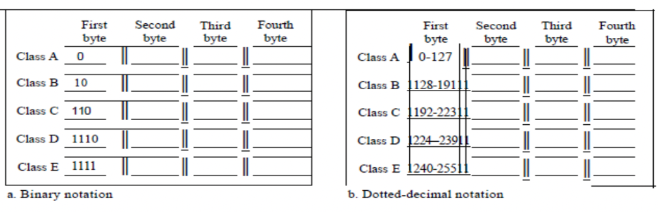
Figure 4.3: Finding the classes in binary and dotted-decimal notation
Classes and Blocks
A limitation of classful addressing is that each class is partitioned into a predetermined number of blocks, each with a fixed size, as seen in Table 4.1.
Table 4.1: Number of Blocks and Block size in classified IPv4 address
|
Class |
Number of Blocks |
Block Size |
Application |
|
A |
128 |
16,777.216 |
Unicast |
|
B |
16,384 |
65,536 |
Unicast |
|
C |
2,097,152 |
256 |
Unicast |
|
D |
1 |
268,435,456 |
Multicast |
|
E |
1 |
268,435,456 |
Reserved |
Historically, when an organization solicited a block of addresses, it was allocated one from class A, B, or C. Class A addresses were intended for substantial companies with numerous connected hosts or routers. Class B addresses were intended for medium-sized enterprises with numerous connected hosts or routers. Class C addresses were intended for small companies with a limited number of connected hosts or routers. The defect in this design is evident. A block of class A address is excessively huge for nearly any business. This indicates that the majority of class A addresses were squandered and remained unused. A block in class B is excessively huge, likely beyond the capacity of numerous firms that obtained a class B block. A block in class C is likely insufficient for numerous businesses. Class D addresses were specifically formulated for multicasting purposes. Each address in this category serves to delineate a certain set of hosts on the Internet. The Internet authority inaccurately forecasted a necessity for 268,435,456 organizations. This event did not occur, and numerous addresses were squandered as well. Finally, class E addresses were allocated for prospective applications; however, only a limited number were utilized, leading to more address wastage.
1.4. Differences Between Intranet IP Address and Internet IP Address
|
Feature |
Intranet IP Address |
Internet IP Address |
|
Scope |
Used within a private network |
Used for global communication |
|
Accessibility |
Only accessible within the organization |
Accessible from anywhere on the internet |
|
Assigned by |
DHCP server within the local network |
Internet Service Provider (ISP) |
|
Security |
More secure, protected from external threats |
Vulnerable to cyber threats if not secured |
|
Example |
192.168.1.20 (private) |
102.45.67.89 (public) |