
Computer Architecture
1. Computer Architecture
- 1.0 Introduction
Computer Architecture and Organization is a foundational subject that explains how computers are designed and how they function internally. It focuses on the structure, behavior, and working of the computer system at a low level, bridging the gap between hardware and software.
1.1 What is Computer Architecture?
Computer Architecture refers to the logical structure and functional design of a computer system. It defines how the CPU, memory, and input/output devices are organized and how they interact to execute programs. At the heart of any computer is the CPU (Central Processing Unit), which executes programs by processing instructions and data.
What is a Program?
A program is a set of instructions written in a particular language that the CPU executes one at a time. These instructions are stored in memory, and the CPU fetches them for execution.
In memory, we have two main components:
- Programs (Set of instructions) - what the CPU must execute.
- Data - the information that is processed by the program.
1.2 Components of the CPU
i. Control Unit (CU): Coordinates all CPU operations. Directs the movement of data between the CPU, memory, and input/output devices. Manages the instruction cycle (fetch -> decode).
ii. Execution Unit: Responsible for executing instructions. The execution process involves three stages:
Fetch: Get the instruction from memory.
Decode: Understand what the instruction means.
Execute: Carry out the instruction
Note: Fetch and Decode are managed by the Control Unit; while, Execution is carried out by the Arithmetic Logic Unit (ALU).
iii. Registers: Temporary storage areas inside the CPU. Hold instructions, addresses, or data that are being processed. Very fast and close to the ALU and CU. There are five (5) types of registers as explained in Figure 1.1.
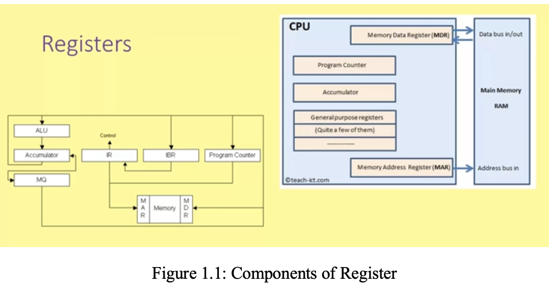
▪ Accumulators: stores the results of calculations made by ALU.
▪ Program Counter (PC): keeps track of the memory location for the next address to be executed. The program counter then passes this next address to the memory address register (MAR).
▪ Memory Address Register (MAR): stores the memory location for data or instructions that needs to be fetched from memory or stored into memory.
▪ Memory Data Register (MDR): stores any data or instructions fetched from memory or any data that is to be transferred to, and stored in memory; that is, MDR holds the data/instruction.
▪ Current Instruction Register (CIR): stores the most recently fetched instruction while it is waiting to be. decoded and executed
1.3 Memory Hierarchy
i. Primary Memory (Main Memory) includes: RAM (Random Access Memory) - temporary, volatile storage.
ROM (Read-Only Memory) - permanent, non-volatile storage; both are located on the motherboard and connected directly to the CPU.
ii. Secondary Memory (Storage): Used for long-term storage of programs and files. - Examples: Hard drives, SSDs, floppy disks, USB drives.
iii. Cache / TCM (Tightly Coupled Memory)
- Cache Memory: The fastest memory, built using SRAM (Static RAM). Stores frequently accessed data for quick use. Often layered (L1, L2, L3) close to or within the CPU.
- TCM: Special cache memory directly connected to the CPU. Ideal for real-time processing, where timing is crucial. Offers deterministic execution.
1.4 Input and Output Devices (I/O)
i. Input Devices: Allow users to send data into the computer. Examples: Keyboard, mouse, microphone, scanner.
ii. Output Devices: Display or produce the result of processed data. Examples: Monitor, printer, speaker.
I/O Devices like touchscreens can function as both input and output.
1.5 The System Bus
The system bus is a group of wires or lines that connect various parts of a computer to transfer data and signals. It includes:
i. Address Bus: Carries memory addresses from the CPU to memory and determines how much memory the CPU can access (e.g., 32-bit vs. 64-bit).
ii. Data Bus: Transfers actual data between the CPU, memory, and I/O. The width of the data bus (e.g., 32-bit or 64-bit) determines how much data can be moved in one cycle.
iii. Control Bus: Carries control signals like Read, Write, and Interrupts and instructs memory and devices on what action to perform.
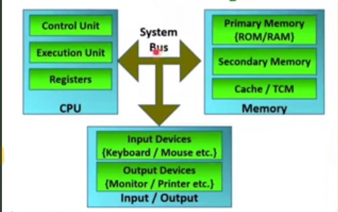
Figure 1: Key Components of CPU
1.6 TYPES OF COMPUTER ARCHITECTURE
Two key types of architecture used in designing computer systems are: Von Neumann Architecture and Harvard Architecture.
1. Von Neumann architecture is a computer design model where the program instructions and data share the same memory space and the same system bus for communication with the CPU. The CPU executes instructions one at a time using the Fetch → Decode → Execute cycle. Instructions and data are stored together in primary memory (RAM/ROM). The Control Unit fetches both instructions and data from memory over the system bus (data bus, address bus, and control bus). Registers temporarily hold data or instructions during execution. The ALU carries out arithmetic and logic operations as illustrated in Figure 1.2. However, since data and instructions share the same bus, the CPU can only fetch either an instruction or data at one time, causing a bottleneck in performance. Key features of Von Neumann architecture are:
-Single memory for both instructions and data
- Uses one bus for both data and instruction fetch (this bus is shared)
- Instructions are fetched and executed sequentially
- Simplified design and cost-effective
- Commonly used in general-purpose computers (e.g., desktops, laptops)
Main memory of Von Neuman Architecture consists program and data in the same memory. So common systems bus is there for program and data access.
Control Unit of Von Neuman Architecture provides timing control, instruction fetch, instruction decode, pipelining, memory access
Register of Von Neuman Architecture holds data and it can be operand of ALU. It is very fast in accessing data with memory e.g general purpose registers, flag register, stack register, program counter etc.
ALU performs all the arithmetic and logical tasks.
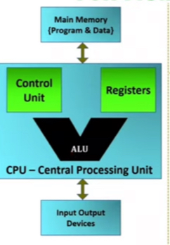
Figure 1.2: Function of Von Neuman Architecture
2. Harvard architecture is a model where the instruction memory and data memory are separate, and each has its own bus for communicating with the CPU. The CPU receives instructions from instruction memory and data from data memory through dedicated buses. The Fetch and Data Access stages can happen in parallel, improving performance. Harvard architecture is ideal for real-time systems, where timing and speed are critical (like in your explanation of TCM). The key features of Harvard architecture include:
- Separate memories for data and instructions;
- Separate buses for data and instructions;
- The CPU can fetch data and instructions simultaneously;
- Faster and more efficient than Von Neumann; and
- Commonly used in embedded systems, microcontrollers, and digital signal processors (DSPs).