Computer Organization
Computer Organization deals with the operational units and their interconnections that realize the architectural specifications of a computer system.
1. Computer Organization
Computer Organization
2.1 Definition of Computer Organization
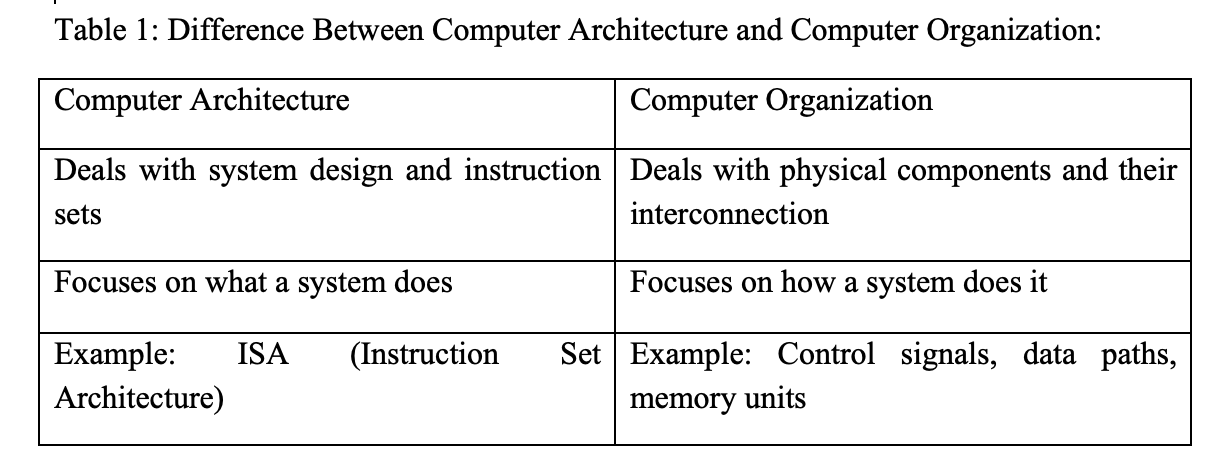
Computer Organization deals with the operational units and their interconnections that realize the architectural Introduction to Computer Organization of a computer system. Computer organization deals with the internal hardware setup that implements a system’s architecture as highlighted in Table 1. That is; it deals with hardware components and how they interconnect and function. Includes the CPU, memory, buses, I/O, and instruction cycles. A well-organized computer design improves performance, efficiency, and expandability.
2.2 Basic Functional Units of a Computer
A computer can be broken down into five main functional units:
• Input Unit - Accepts data and instructions from the user.
• Output Unit - Displays or outputs processed data.
• Memory Unit - Stores data and instructions before, during, and after processing. We have two (2) types of memory in a computer:
i. Primary memory which is the RAM and ROM and are fast, volatile (except ROM) and temporary
ii. Secondary Memory e.g HDD, SSD; they are slower but permanent and larger in size
• ALU (Arithmetic and Logic Unit) - Performs arithmetic and logic operations.
• Control Unit - Directs processor operations and coordinates components.
• CPU - Combination of ALU and Control Unit; brain of the computer.
The performance factors in computer organization depend on the clock speed (Higher speed = faster processing), word length (Longer words allow more data to be processed), bus width (Wider bus can transfer more data at once), cache memory (Reduces access time to frequently used data).2.3 Data Path and Control Path
Data Path:
- Carries data from one part of the processor to another.
- Includes ALU, registers, and buses.
Control Path: Manages control signals and timing.
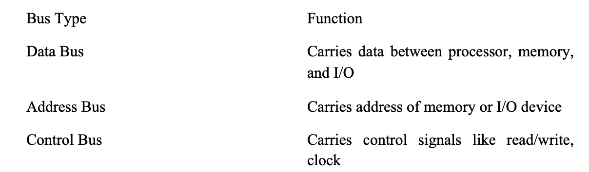
2.4 System Bus
A bus is a communication pathway connecting different components.
Types of Buses:
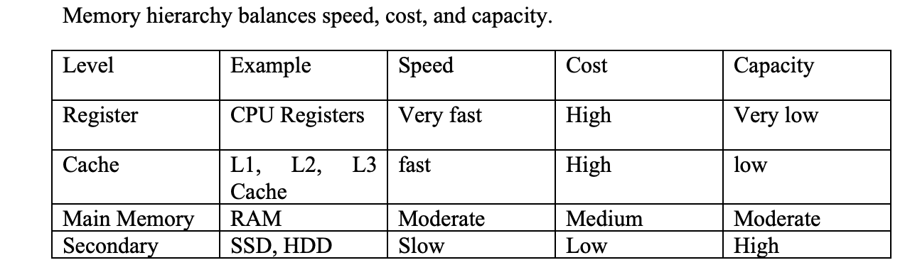
2.5 Memory Hierarchy
2.6 Instruction Cycle
Instruction Cycle include Fetch-Decode-Execute as earlier discussed in Module One
Stages of Execution:
1. Fetch - Retrieve instruction
2. Decode - Interpret the instruction
3. Execute - Perform the operation
4. Store - Save result (if needed)
This cycle continues repeatedly during program execution.
An instruction is composed of opcode (operation code) and operands (data/addresses). Types of Instructions: Data transfer, Arithmetic, Logic, Control flow.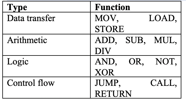
2.7 I/O Techniques
the techniques include: Programmed I/O, Interrupt-Driven I/O, DMA.
• Programmed I/O: CPU actively waits for I/O operation to complete.
• Interrupt-Driven I/O: CPU is alerted when the I/O device is ready.
• Direct Memory Access (DMA): Device can access memory directly, bypassing CPU.
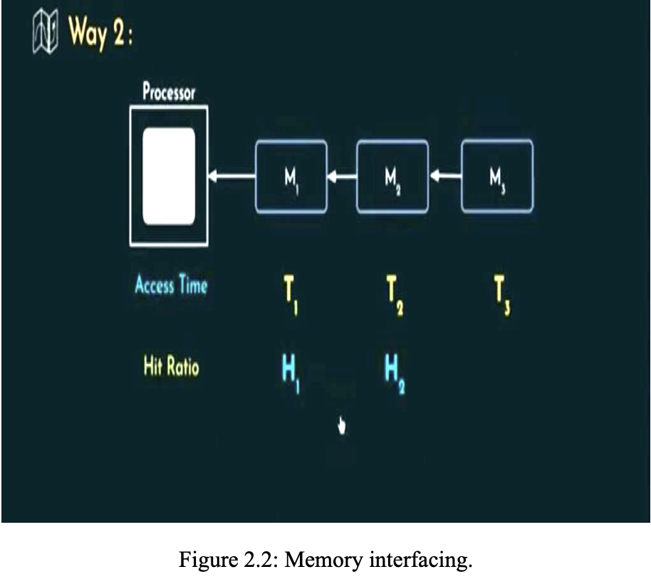
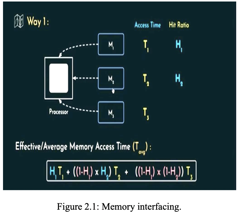
2.8 Memory Interface
Memory interfacing is a computer organization that deals with way of connecting various levels of memory units to the processor and I/O peripherals. Memory interfacing can be done in two ways. All the different Memory levels are simultaneously connected to the processor and whenever the processor wants some information, it can look for it in all the different levels side by side as demonstrated in Figure 2.1.
The memory units’ level is interface one at a time. that is, if the required instructions cannot be found in M1, then the processor check for the instructions in the next level i. e M2 and if not then the next level M3 as shown in Figure 2.2.